RCA 1802 (Retrochallenge 2017/04)
Retro Challenge 2017/04 Main Contest Page
Update 8-28-2017
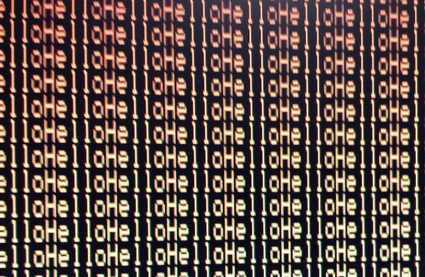
I haven't worked on this in a while. Recently I started back up and got RS-232 communication working in the opposite direction: The COSMAC can receive bytes from the PC! I have a short program that waits for a user keypress, then echos "Hello" from the, but replaces the 2nd letter in the string with whatever key the user pressed. Hello becomes Hallo, Hbllo, etc. So it works. But, there is a small problem: The COSMAC can't send and receive at the same time. At least, my simple serial routine can't. So if I type a key while the COSMAC is sending, it is not received, or worse, it receives an incomplete byte and received garbage. This isn't a HUGE problem, in that in a traditional command-line environment, the user could wait until the display is idle and prompting for input. I have been thinking about how to make a full-duplex routine, and think as long as I poll the serial port at least twice per bit period, I should be able to catch the stop bit and receive and send at the same time. This might be tricky. That's what I get for not using a UART.
Also, so far, all of my programs have been assembled using a program called A18. I originally found this program on Herb Johnson's web site, http://www.retrotechnology.com/memship/a18.html. When I first started out, I was entering programs on the front panel, so I wanted a human-reable binary listing. I modified the assembler to print out the listing file in both the original hexadecimal and in binary text. I also modified it to print out one byte per line, so it is easier to keep track of where you are. When then disassembly has multi-byte instructiuons on the same line, it was easy to get off-track when switching in by hand; at least on a novice switcher like me. Old-hat Altair users may laugh at my poor switch-flipping skills. Later. after I hacked-up the PC parallel port interface to automate pushing bits around, I also added the option to output the assembled program as a raw binary file (not a text file), which the parallel-port program can read. I wanted to release my changes to the internet. It turns our Herb Johnson isn't the original author of A18, but instead a contributor to an open source assembler that was originally published via the C User's Group. I contacted the original author, William Colley, and got permission from him to release A18 under the GPL. I now have the original, and my modifications, on Github.
More Serial Communication 5-13-2017
I tried to write a more general-purpose serial output routine that read a byte from memory and shift it out. I almost got it working, but editing code through the front panel is hard. Without the ORC's address display and overwrite-no-increment button, it would have been exceptionally annoying: Whoever used a base, ROMless ELF back in the day had to have been insane.
I automated entry of code from the front panel by an old PC's parallel port. The PC has 8 bits out, plus a strobe bit, so it is perfect to automate the switches and entry button. I modified the A18 assembler to output a file of raw bytes, and wrote a short program on linux to pass the bytes over the parallel port of my old PC.
After a few short iterations, I got a working serial routine. I wasn't that far off from the final version; If I continued using the front panel I would have eventually got it, but it would have taken all day. Here is the final code:
The above outputs:
The next logical thing to do is to write a serial receive routine, and a short program that prompts for a word of text and then repeats it back to the user. Once I have a full serial driver written, then I can write a simple bootloader. I got a package in the mail with some EEPROMs, and a few other things. I also got a 2 Mhz crystal oscillator, so we'll see how this works at 'high speed.' The serial timing for 1Mhz is 300 Baud, if I run at 2Mhz, I won't change a thing in the program; it'll just run at 600 baud. The COSMAC is rated at 2.5 Mhz, and my SRAM and other 74HCxxx chips are faster than what the COSMAC originally used.
Serial Communication 5-9-2017
I finally got the timing right to transmit a single byte out of RS-232:
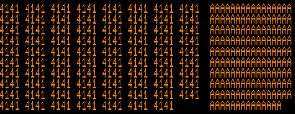
I spent over an hour trying to figure out WHY everything was so messed up coming out. I couldn't get the timing right, I kept getting 0b10000010 instead of 0b01000001. I thought the framing was off. When I messed with the timing, I could stretch out the bits, 0b11000111, etc. I thought I counted the cycles correctly. It turns out the timing was perfect, and RS-232 is LSB first! Not MSB first! Don't know why I thought it was the other way. I was receiving my bits in the right time, just sending them out in reverse order!
I put the delay value up near the top of the program, so I could easily ram-edit it without changing it in multiple places. Having the address bus display LEDS, and the write-here (instead of just increment-write) features of the ORC really made this is a lot easier.
Here's the assembly code:
Everything below this line is 'legal' for the retrochallenge judging. Everything above this line is just me continuing to goof around on my own time.
Update 4-30-2017 9:24 pm Local Time
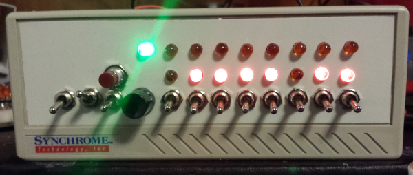
COSMAC ORC!
I came up with a stupid name for my stupid computer: I will be calling it the ORC, as it isn't quite an original ELF. Here is it running:
Schematic
[Click Here, it's big]![[Click Here, it's big]](ORC-bw.png)
Differences from the orginal ELF
- Address display: The original ELF had you counting/guessing where you were. Loose count, go to the beginning
- Write without preincrement: If data at an address is being displayed while stepping through in Write Protect mode, WP can be disbaled, and a write can be forced at the location. In an ELF, after stepping through memory to review code, and a mistake is found, you must restart at address zero and count 1 less then where you want to modify.
- True data bus display: On the original ELF, the Hex display (later replaced by a binary display in modern clones) is a latched output port. The ORC is designed to be incorporated into a more I/O environment, so all 7 possible output devices are left free.
- The EFx line is not tied to the input button: All 4 EFx lines are available for other uses
- The ORC is evil. If the DMA pointer is not moved out of the way, and the LOAD button is pressed while running, memory will be overwritten by whatever is on the bus.
- The ORC is evil. If the Write button is pressed while a program is running, whatever data is on the bus will be written at whatever address is on the bus.
- Simplification: The front panel data switches are not selected in via control signals a buffer. They simply pull the floating data bus bits high or low. When using in INput instruction and a particular device is no not connected, or when the computer is in manual load mode, the bus is otherewise floating, so the switches take over. When other devices drive the bus, the 10k resistors are no match for it.
- BUG: When write protect is ON, pressing the load button sometimes bounches and one address is incremented on both press and release of the button. This is easy to work around, when you are 1 less than the address you want, press and hold, make the write, then release. I suspect the crappy RC debounce I am using on that button, however, it never does it when write protect is OFF, and its the same button!
- Potential BUG: I am not 100% sure the 'write here' functionality I added is correct. The low address isn't latched, and I don't know of the COSMAC actually drives the address all 16 clocks of the machine cycle! It seems to mostly work, but I might adjust it later.
Planned enhancements (future retrochallenge?)
- Add latches and N-bus decoding for GPIO. Then this becomes potentially useful :-)
- More then 256 bytes of RAM
- RS-232 serial port. Bitbang via Q and EF1. (Just 'software', as the TTL levels of theses signals are already exposed to a header on the board)
This was a lot of fun! Good luck to anyone else doing the retrochallenge.
Update 4-25-2017
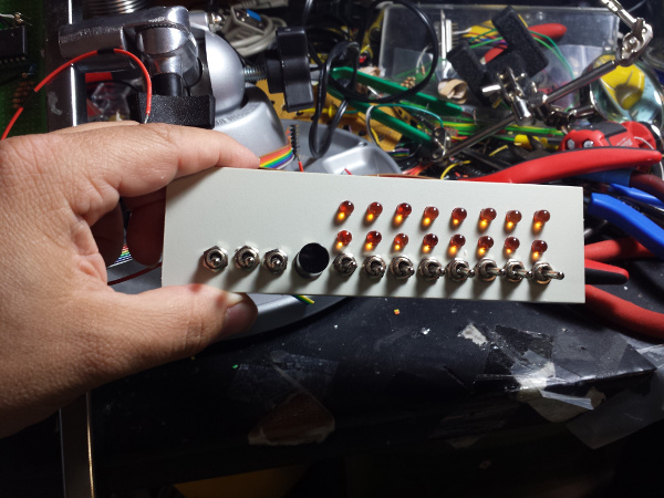
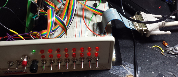
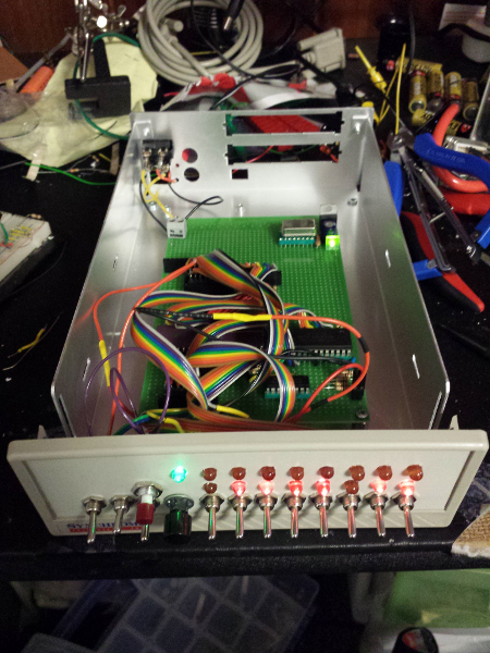
This is what the front panel looks like. The top row of LEDs are the low byte of the address. This is to help keep your place during program entry. The bottom row of LEDs are the data bus. At present, this is whatever is on the data bus; it is NOT a latched output port like it is on the ELF. The push button is inserts the right 8 switches into RAM as a byte. The left three switches are CLEAR, WAIT and Write Protect. I actually forgot to add put a hole in for Q, so I'll drill that next. There's also plenty of room to add other indicators and switches if needed.
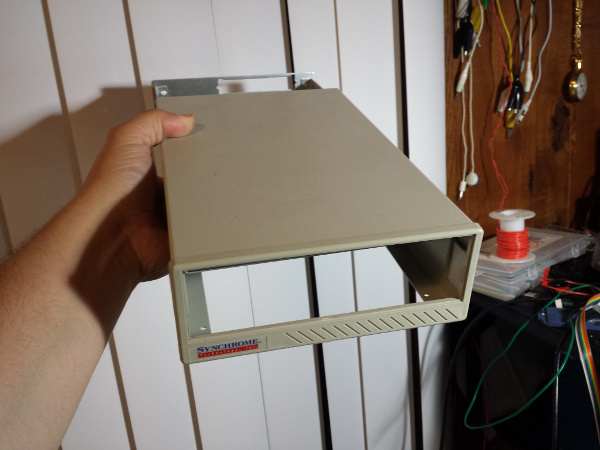
This front panel fits snugly in where this external CD-ROM drive used to be. My immediate goal for the retrochallenge is to get this boxed up, and demonstrating it running a program input by the front panel.
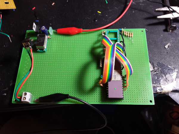
Update 4-19-2017
I moved all the ICs to the perfboard. All that remains are the passive components that made up the 'front panel.' The address line LEDs are not connected, but the Data lines are. I blind-switched in a 4 byte program to turn port Q on and off. When I run the program, and halt the processor, the Q line is randomly high or low. When it is running the LED on the Q line is at half brightness, and if I halt, its either full on or full off. So, I suppose the CPU is running programs just fine. Good to know I didn't break it when moving it over. That's the part of projects I hate the most: going from something that works on the breadboard to some soldered thing that doesn't. Now I need to build a proper front panel.
I need to start deciding the layout of the panel. I need 8 data input toggle switches, and 3 more toggles: write protect, WAIT and RESET. 8 data bus LED lines. One pushbutton for data input strobe. I would also like to have at least 8 address lines to help keep your place when entering a program, something the original ELF didn't have.
Update 4-18-2017
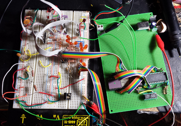
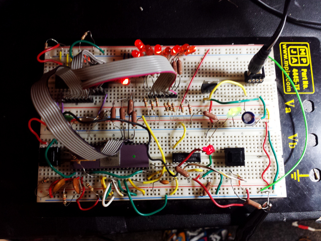
You want to see a mess?:
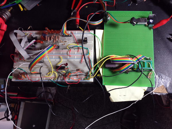
I started moving the circuit from the breadboard to a prototyping board. I connected a few key lines up to the breadboard (SC1, DMAIN, ADDR0, ADDR1, WAIT, CLEAR), and verified that if I trigger a load event, ADDR 0 and 1 will count out 00, 01 10 11, and then roll over to 00. The chip is not hot, no smoke escaped. Wiring up the rest should be pretty easy and I should have a COSMAC running in a permanent configuration soon. I did not have as much time this last weekend as I would have hoped, so I am working on it an hour here, hour there, whatever I can steal away from weeknights.
The circuit has the RAM socket wired up to the processor using rainbow ribbon cable. Only address lines 0-7 are connected, and the rest are on pullups. Until I can load in a program longer than 256 bytes (which means I have a bootloader running on here accepting input form a PC), there is no reason to access the higher RAM addresses.
Update 4-13-2017
Instead of soldering, I decided to try to write a more complicated program. I downloaded the A18 cross-asembler from retrotechnology.com I created a program that toggles the Q output on a delay. In this Youtube video, you can see me halt the process, change the delay loop constant in the code, and restart it.
The source listing is here:
        INCL    "1802reg.asm"

;comment

START   ORG     0H
        SEX     R2      ; the R(X) register is 2
        LDI     0       ; D is zero
        PHI     R2      ; R2 HIGH is zero
        LDI     200
        PLO     R2      ; R2 LOW is ZERO
LOOP    DEC     R2
        GLO     R2
        BNZ     LOOP
        LSNQ            ;skip2 if Q zero
        REQ
        LSNQ            ;skip2 if zero (it now is zero)
        SEQ             ;set Q
        NOP
        BR START


        END START
It is probably not the fastest or best way to do this, but this is my first venture in 1802 programming other than the 3-statement loop I ran a few days ago. I really need to solder this into a perfboard, and then try loading in longer programs over some 9-bit (data+strobe) bitbang interface, like a PC parallel port or Arduino. Once I can run longer programs, my goal is to create and debug a small serial bootloader. Something small enough to switch in by hand, and then load the rest off the serial port. If I only care about reading, and I'm not checking parity, then all I have to do is wait for a start bit and then sample 8 times with the correct delay, write the byte to memory, and wait for the next start bit. The bootloader will do this for a fixed number of bytes, similar to the very tiny Altair bootloader. Then I can boot a more complex monitor program off the serial port: This would be like the Altair checksum loader.
Update 4-11-2017 2
I got a 1MHz "canned" oscillator that now runs the COSMAC at 1Mhz. I tried out the same test program as before, except now instead of having to press "CLOCK" 8 times to load a byte, I just have to press it once. I will have to try a longer program. The next thing I want to do is bitbang serial output over the Q port, the same port the LED is connected to. If I want to run anything longer, I will need top bitbang over an Arduino or PC parallel port. That feels like cheating though. Its already 1/3 of the way through the month, so I think I better start soldering this onto Perfboard tomorrow night :-) The main circuit has been proven, everything else is just expansion. I have not put the latch on the upper address bits of the RAM yet, but I don't expect that to be a problem to add later. The unused address lines will just be on pullups, and if the latch is ever added, they will harmlessly sit there. I am NOT going to be inputing greater than 256 byte programs by hand! That's not just be being lazy: The COSMAC loader mode doesn't output the high address strobe, so I don't think you CAN key in a greater than 256 byte program.
Update 4-8-2017 2
I wired up a junky switch panel and put in a 4-byte program
SEQ 7B  0111 1011  Set Q (Turn LED on)
REQ 7A	0111 1010  Reset Q (Turn LED off)
BR  30  0011 0000  Short branch (within this page)
    00  0000 0000  Branch target (address 0)
Update 4-8-2017
I have discovered a method of programming a microprocessor worse than front panel switches
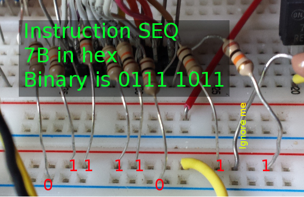
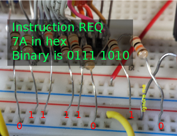
By manipulating the pullup resistors on the bus to pulldowns, I can create bytes on the bus. I connected the SRAM and COSMAC data busses. I inputed the SEQ instruction at address 0, which is supposed to turn the Q port on, and the REQ line at address 1, which turns the Q port off. An LED connected to the port does indeed turn on for a short time and then back off, if I reset the processor and step the clock manually. I just programmed a microprocessor from scratch!
The next steps are to build a front switch panel, even if a temporary one from junk. I have some nice switches I can use, but I am not decided on a case yet, so I will just mount them on whatever junk I have, intending to move them later. Once I can switch-in short programs without having to poke/unpoke wires in the breadboard, I will also automate the clock. I can use a crystal oscillator later, for now I think I will use a 555 timer and keep everything in the KHz.
Update 4-6-2017
edited 4-7-2017I have a very messy breadboard with memory partly wired up. I only have the bottom 8 address lines connected to the SRAM, from the CPU, and no data lines connected. I have LEDs on the SRAM data lines, and 10k pullups. This leaves the LEDs a dim 0xFF when the RAM is in tristate. The /WE and /OE lines are not connected to the CPU, but instead manually activated by poking at the breadboard. The CPU's /MEMRD and /MEMWR lines are connected to LEDs, and blink as I expect. When the CPU commands a write on the LED, and I manually pull /WE down, the pullup value 0xFF is stored in the specified memory location. When the CPU commands a read, and I manually pull /OE down, the previously written 0xFF appears on the SRAM bus. If the CPU goes to an address that I did not write to, the random initialized SRAM 'garbage' appears.
Soon I will connect the data lines and /WE, /OE. I didn't want to do it all at once, since I wanted to watch the timing clock-by-clock, and make sure I understand the bus correctly. I do not want the CPU and memory to try to output to the bus at the same time.
If I step through the bootloading DMA sequence, the address lines on the memory and /WE lines change as expected. If I hook up the data lines, I should be able to step through each address and write a program to memory 1 byte at a time.
Since the pullup resistors seem fine to write values into the SRAM, I have an idea to simplify program loading. When I look at the ELF schematic, there is a buffer from the switches which is tristated when the SRAM or CPU has the bus. I feel this is unnecessary: When a program is being written into memory, both SRAM and the CPU are in tristate, so any pullup resistor will be the value that is written. If the front panel switches are SPDT, there can be a selection between pull-up and pull-down. If other input devices are added, they should be on tristate buffers and function as the SRAM does. I need to do more reading on the I/O mechanisms, but as long as I can get programs in (a byte at a time), and I can read/write SRAM, everything is set. We can always do memory-mapped IO.
Parts so far:
(Not counting minor things like resistors, etc.) (Links to datasheets were for whatever versio I found first. My chips are old and from unknown sources, so who knows what manufacturer it's supposed to be.)- CDP1802
- MC14027 CMOS JK flip-flop (claims is replacement for 4027, so maybe use that instead)
- LH52N256 32KX8 SRAM Really, any CMOS-level compatible asyncronous SRAM will work. I have a couple of these chips laying around. I don't have any of the 4-bit SRAM laying around, and I'm trying to build mostly from whatever CRAP I already have. That, and 32K is a lot of space!
Update 4-5-2017
Now I understand why Joseph Weisbecker used a D latch in his Popular Electronics article. I didn't have a 4013 to use as a latch, so I decided to wire one up with a 4011 NOR gate. I successfully made a SR latch, and hooked 'S' up to a button and 'R' to the 1802's SC1 line, which turns off DMA. When I single-step the clock, it works perfectly: I press 'S' and ~Q goes low. The 1802 starts a DMA cycle, /WE goes low, SC1 goes high, hitting 'R', and the ~Q goes high again, keeping a second DMA cycle from happening. But, when I hold down 'S' and step through the clock many times, which is what would happen if the clock was running and a human were holding a button down, as soon as SC1 goes now, the SR latch 'see's that S is still low and starts another DMA cycle. This is not What I want.
When you look at the COSMAC ELF schematic, you can now understand the unusual use of the D-latch. A D-latch copies the D input to the output Q at the rise of the clock. 'S' will set Q to high immediatly, and 'R' will set Q low immediately. And of course ~Q is always the opposite of Q. This is how the latch works in the original design:
- User presses the input button. This is tied to the CLOCK input of the latch. On the rising edge of the press (when the user presses the button, not when the button is held down!), the D input is latched into Q.
- The D input is tied to a constant high value. This means whenever the user presses the button, Q becomes 1, and ~Q becomes 0.
- ~Q is connected to DMA-IN. So evertime the user presses the button, DMA-IN is pulled low, starting a DMA cycle.
- The 1802 Pulls SC1 high during a DMA cycle. SC1 is connected to the 'R' pin of the latch, which resets the latch immediately. SC1 will end the DMA cycle.
- If the user is holding down the button at this time, it does not matter, since the button is the edge-triggered clock input.
- 'S' is not used, and tied to ground.
Too bad I don't have a D flip flop. I did look around, and I did find a 14027 JK flip flop in my colletion. A JK flip flop can be made to mimic a D flip flop. After some fiddling around, I got an arrangement that works how I want. I can press the input button, and hold it as long as I like while I step through the clock, and it will only go through one DMA cycle. I had trouble where sometimes letting go of the input button causes a second cycle. This would be the infamous 'switch bounce.' I put the input button an a RC filter, and its seems debounced good-enough for now. Now that the memory address and control lines do what I want, next is wiring memory.
Update 4-4-2017
I spent some time today reading about the 1802. On the breadboard I put LEDS on the address lines, /MRW and /SC1. This allowed me to play around with the /WAIT, /CLEAR and /DMA lines to understand the bootloader timing. The 1802 had a built-in bootloader mode, where if both CLEAR (reset) and WAIT are pulled low, the machine will write the data bus to RAM 1 byte at a time. Pulling /DMAIN low will write the current bus to memory (basically output address 0000 on pull /MRW low for a couple clocks). Repeated pulling of /DMAIN will increment the address and write additional bytes to memory. When the bootloader is written, the processor can be reset to address 0000. One the the things I was trying to understand was the necessity of a flip-flop when loading, such as what the COSMAC ELF does. It turns out that if /DMAIN is pulled low, and kept low, the processor will continue to write the same value to subsequent memory locations. What the flip-flop in the ELF does is release the hold on /DMAIN with the SC1 output of the processor goes high. The original author chose a 4013 D type flip flop for this.
I would like to connect a small RAM to the processor and hand-key in a program with switches. To do this, I will either have to single-step the processor by hand and manually pull /DMAIN up and down at the correct times, OR I can use a flip-flop. A regular S/R should do this fine: Pressing 'IN' will set it, and SC1 will reset it.
I am probably the only person in a long time who has looked at the COSMAC ELF design, and instead of just building it as-is, is instead trying to simplify it even further.
- Membership Card Schematic
- Modern 1802 Variant Datasheet
- RCA 1802 Manual from 1976
- Original Popular Electronics ELF article
Update 4-3-2017
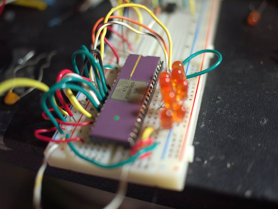
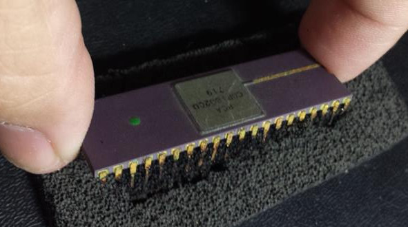
The 1802 chip I salvaged still appears to count when hardwired to NOP.
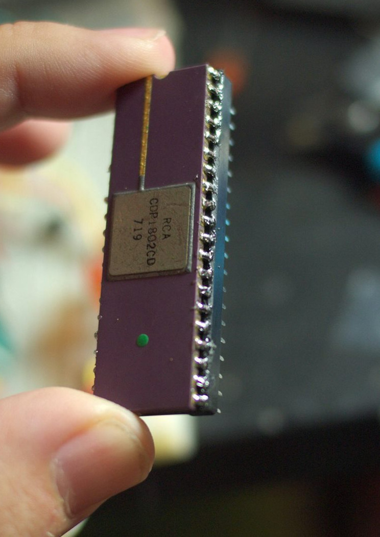
Starting April 1, I will be working with a RCA 1802 microprocessor. I have 3 of these, and they were very badly stored. The anti-static foam reacted with the pins, and just ate them away. A few months ago I took the worst-looking one and attempted to clean it up. Most of the pins fell off! I filed down the pin-stumps until they were nice and shiny, and very carefuly soldered it permanently into a socket. I wired up a breadboard to have a NOP instruction, put LEDs on the address lines, and set up a 555 timer as a slow clock. The address lines blink-counted in binary, proving the CPU was at least partially alive. I then put it away, hoping to someday build a computer around at least one of them.
During the next month, I will revisit this, and attempt to build a computer around this repaired RCA 1802. I will be studying the COSMAC ELF designs online, but will probably make a few changes.
Damaged RCA 1802:
Recovered RCA 1802:
Running RCA 1802: