Re-Calculate TI SR-56 Repair
A while back I picked up an old TI-56 calculator at a flea market. I thought for sure the problem with it was the old NiCd battery pack, and I'd quickly have it up and running. I tried applying the proper voltage to the right spot, and it never came up. I put it in an drawer and forgot about it. A few years later, I decided to have a second look at it.
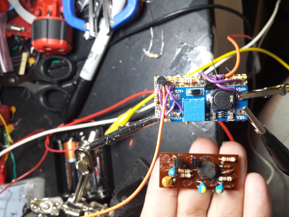
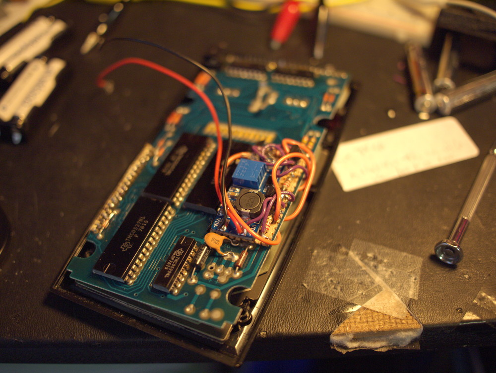
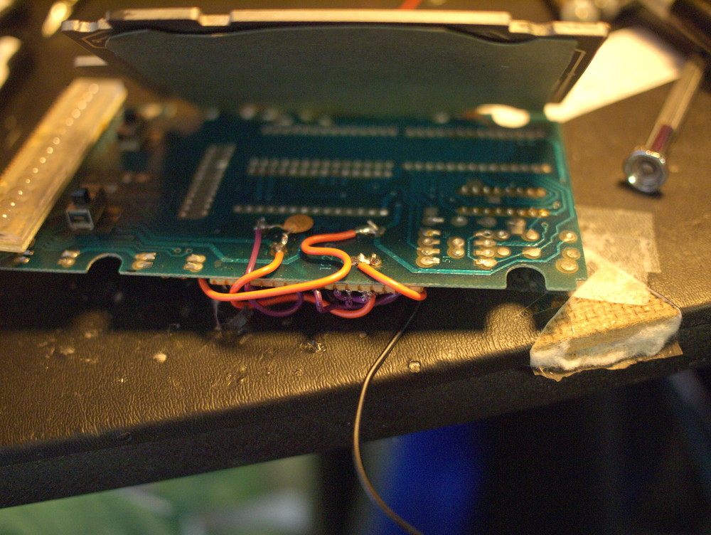
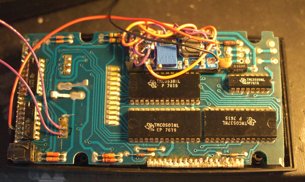
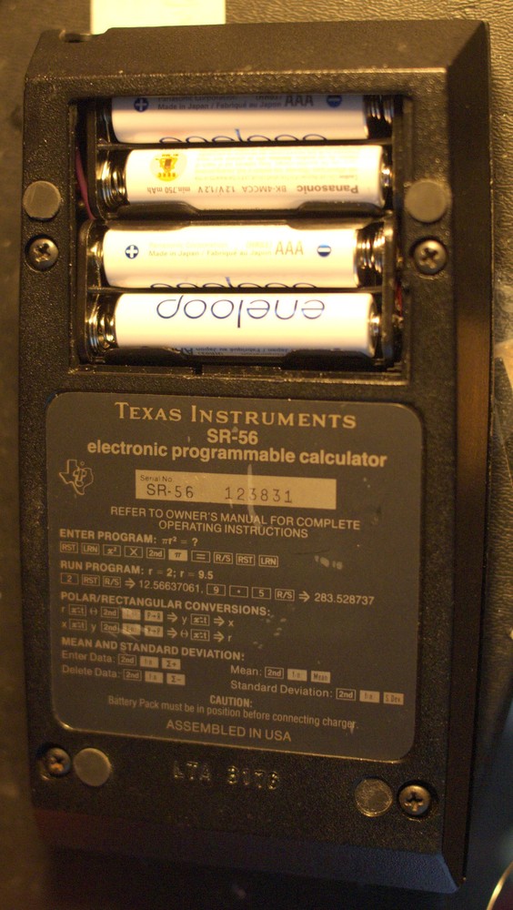
Before I get into all the nasty technical details, pictures first! (Click on any picture to make it big)

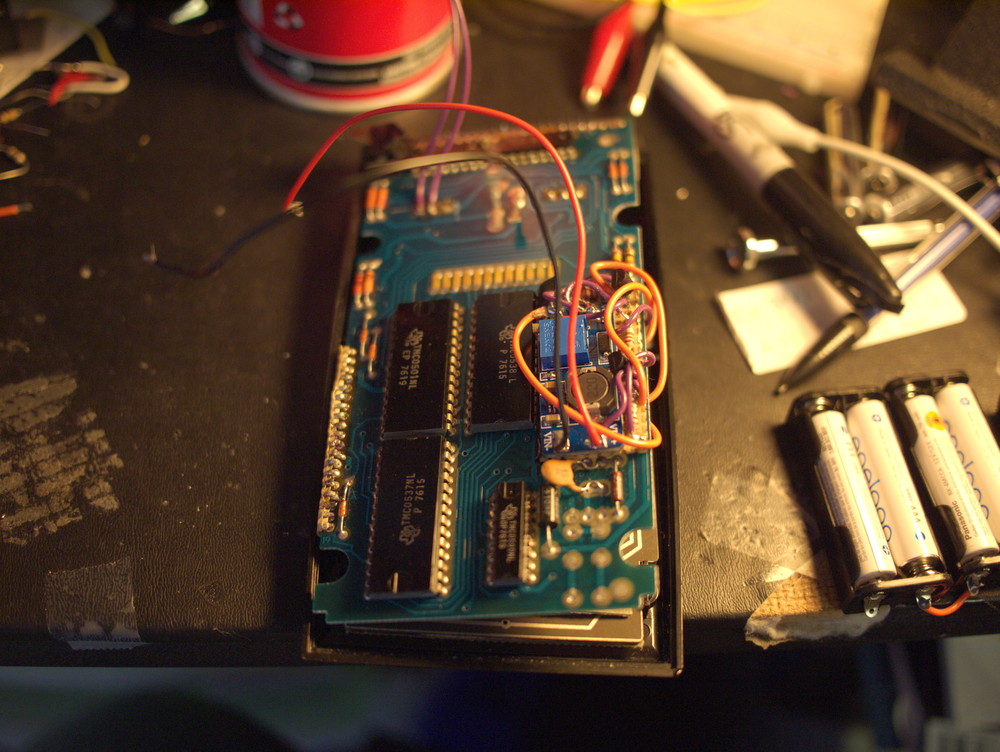

I found a couple of service manuals online for very similar calculators, the SR-50 and the SR-58. (From the excellent rskey.org site) I quickly found out that the power supply board for the calculator did not work. The SR-5x series of calculators are PMOS chips, and run on -15 and -10 volts. This is quite unusual compared to today's CMOS that run on positive 5V and lower. The power supply of the calculator takes the 3.6 volts of the NiCd battery pack (3x1.2v cells) and produces the required voltages.
There was no schematic available for the power supply to help diagnose what was wrong. The SR-50 had the power supply as part of the mainboard, and the SR-58 had the power supply as a seperate module. My calculator (SR-56) appeared to be the same module as the SR-58. The SR-50 manual had detailed info on the power supply, including a schematic, but this didn't resemble my SR-56 at all. The SR-50 power supply appears to be a boost converter with a single inductor. The SR-58 power supply consisted of a two transistor multivibrator and a small transformer I couldn't identify. There appeared to be two seperate secondaries on the transformer, both leading to a diode and capacitor. When powering this up, one of the transistors was hot, and the circuit was not oscillating. One of the transformer leads had come undone, but attempting to solder it did not fix it. Something had gone wrong here, and the SR-58 manual simply stated that if the power supply module was bad to replace it. I was not even sure if these transistors were NPN or PNP.
I decided to try replacing the power supply with something built with modern parts. Online several Amazon and eBay sellers have small adjustable boost converters. Unfortunately they all produce positive voltages relative to their supply, not negative. I did fine one that produces both + and - voltage, but it was too big to fit in the calculator. I ended up ordering a small module from Electronic Goldmine, and adjusted it to 15 volts. Nothing is stopping you from 're-labeling' the +15V out from the boost converter as ground (0V), and relabeling the original ground as -15V. There are a few issues with doing this:
- For most boost converters, the input (-) and output (-) are tied together: These are non-isolated boost converters and the intention is the negative terminals are considered to be ground. If I am renaming the (+) output of the boost converter to be ground, then that makes the (-) for both the battery connection and the boost converter output be -15V.
- The above also means that that battery (+) connection is negative relative to ground. If the battery is 9V, then the battery (+) terminal is 9 volts above its (-) terminal. Since the (-) terminal is at -15V relative to ground, then the battery (+) terminal is at -15V + 9V, or -6V.
- The original calculator circuit labeled the battery (+) terminal as ground, and took all the other voltages relative to this. The battery (-) terminal was considered to be -3.6V. Because I am generating the primary 15V in an alternative way, the new battery powering the boost converted must be connected directly to the boost converter, and not route through any of the calculator's circuitry. In my new design, the battery (-) terminal is considered to be -15V, and battery (+) terminal is not used directly by the calculator, and doesn't directly correspond to any of the voltages the calculator needs.
The calculator also needs -10V. This can be produced from -15V by using a simple linear voltage regulator, such as the LM337. The LM337 is the 'negative' version of the LM317. You may be thinking that you can use a LM317, and set it at 5V. This almost works, since, -15V + 5V = -10V. This will in fact produce -10V, but will not work to power the calculator. If you connected a device between the LM317's generated -10V and the -15V terminal, it will work, because from the LM317's point of view it is generating 5V. But if you connected a device, such as the calculator's PMOS chip, between the generated -10V and GND, from the LM317's point of view, you are connecting a device between it's output of 5V and 15V. It cannot do that, since the output stage of a LM317 is like a diode: The output of a LM317 will flow as long as you are connecting to a lower voltage. The LM337 is built with the 'diode' facing the other way, and works in the opposite way, which is what we need here.
There is one more voltage that needs to be produced: -3.6 V. The original design uses the battery (-) terminal as -3.6V and uses this to power the LED display. I am not using a 3.6V battery, and even if I did, the battery is tied to the 'wrong' end of the 15V supply to use it in this manner. The -3.6V must be produced by a second LM337. In my first attempt, I generated it directly from the -15V supply. This means the regulator was wasting almost 12V. The LEDs, when I display all 8's, took about 100 mA, which amounts to wasting over a watt of power. The 337 got pretty hot. In the second attempt, I cascaded the LM337's, so that one produced -10V from -15V, and the second one produced -3.6 from -10V. This one cooled down, but the first LM337 was now powering both the display and the logic chips. In the final attempt, which ended up being the design I went with, I decided to produce the -3.6V by powering the LM337 directly from the battery. Remember, the (+) terminal of the battery is quite negative relative to the ground of the circuit. If the battery is 9V, the battery (+) terminal is at -6V. Generating -3.6V from -6V is much less wasteful, and produces much less heat. Power usage was also lowered by generating -2.5v instead of -3.6... This only powers the LEDs, and the LEDs seem almost as bright on 2.5V than on 3.6V, but take significantly less current.
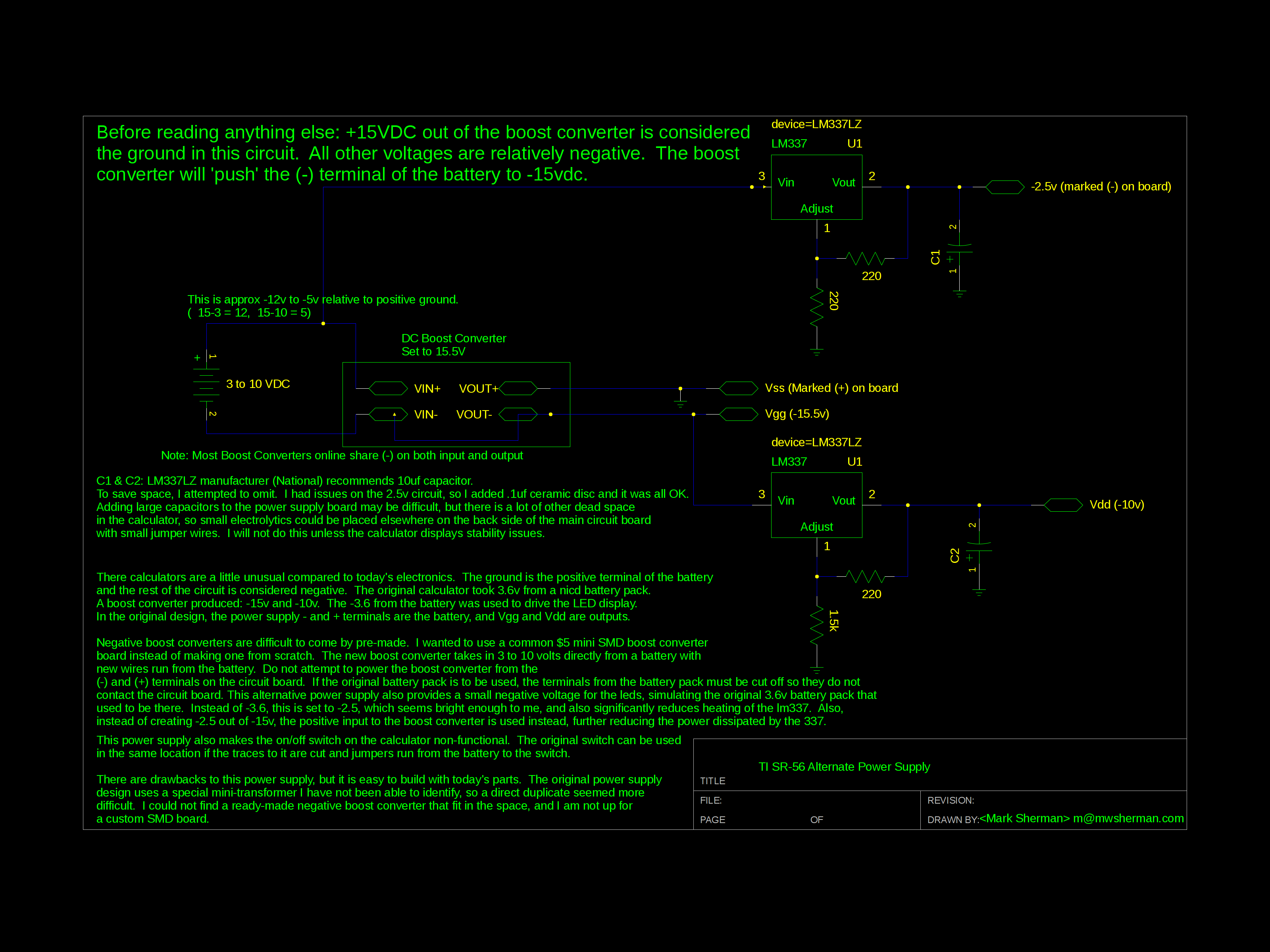
Click here for the final schematic
There was one final detail: the power switch. In the original design, the 3.6V battery powered everything, including the power supply, and was interrupted by a simple switch. In my modified power supply design, the 3.6V (actually -2.5V) is not the power source from which everything else is derived, but instead one of the outputs of the power supply. Interrupting it with the switch doesn't power off the boost converter or calculator logic. To make the original power switch work, I had to cut the traces to it, removing it from the original circuit. The switch was then wired up in series to the boost converter battery.
One advantage of using a boost converter to power everything is the flexibility in power sources. I was able to run this calculator on anything from 3 AA's to a 9V battery. In the end, I managed to fit 4 rechargable NiMh AAA batteries where the original 3 AA NiCd battery pack used to be. The higher the voltage, the less current the calculator takes. Currently the calculator seems to pull between 90 and 200 mA, depending on what digits are on the screen. The AAA batteries I got claim a 800 mAH rating, so this should give at least 4 hours of runtime. The original battery pack was estimated to give about 4 hours runtime as well, so at least I didn't do any worse than TI did 40! years ago.
One final detail: This calculator has a power port for recharging. I taped over this when I put the calculator back together. There may be a way to make this charge the NiMh pack safely, and maybe even run the calculator at the same time when doing this. It would probably involve cutting more board traces. I got this dead calculator working again, and didn't want to risk breaking it again just to avoid taking the batteries out and putting them in a proper charger. I leave this as an exercise to the reader.
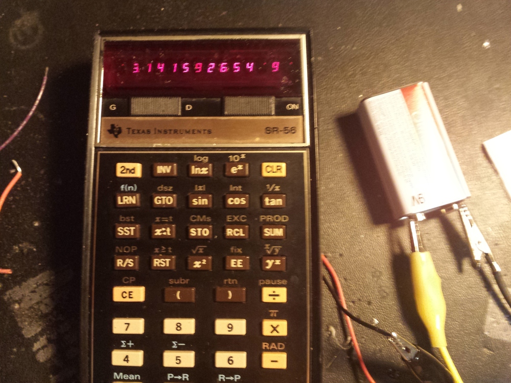
And if any readers try to duplicate this and blow up your calculator, or yourself, I have no claims that this is well-designed or even safe. It seems to work, and I don't see any smoke. That's about all the testing I've done. I've started using this calculator at work and I still have a job, so it seems to give correct answers.